One of the big projects that has occupied our past week is a repair manual for the oxygen concentrators used in the CPAP project. The CPAP machine uses oxygen blended with pressurized room air to deliver flow to the patients at around 50% oxygen. Thus the oxygen concentrators are an important part of the project. Although meant to be durable, every device will begin to fail eventually and the staff available to fix these integral devices do not always have the best training. Thus our goal is to produce a document that not only covers troubleshooting and possible causes of failures, but walks through step by step how to solve the problems and repair the issues. This pictorial manual is geared towards maintenance staff at the district hospitals, who may not have received extensive training.
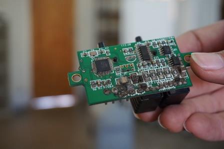
(Picture of an Oxygen Sensor chip from an oxygen concentrator for our manual. You might be able to see where the bottom of the chip is burnt out; this circuit board needed to be replaced.)
My task has been to make a diagram of the pneumatic (air flow) pathway to aid the troubleshooting process. For a technician trying to repair one of these devices, with little prior knowledge, this flow chart is meant to show not only the flow, but also the basic function of each element. Using this diagram, and accompanying description, one can follow along with the broken oxygen concentrator and make sure there are no leaks at any point. While some of the main repairs require spare parts (see my earlier blog post), there are some simple interventions that we address in the manual. For example, leaks or failures in the tubing could be repaired without spare parts and without strong technical knowledge. Therefore, I want the pneumatic diagram to be as user friendly as possible, so, while it is still a draft, I would love to hear any feedback you have on anything that is not clear.
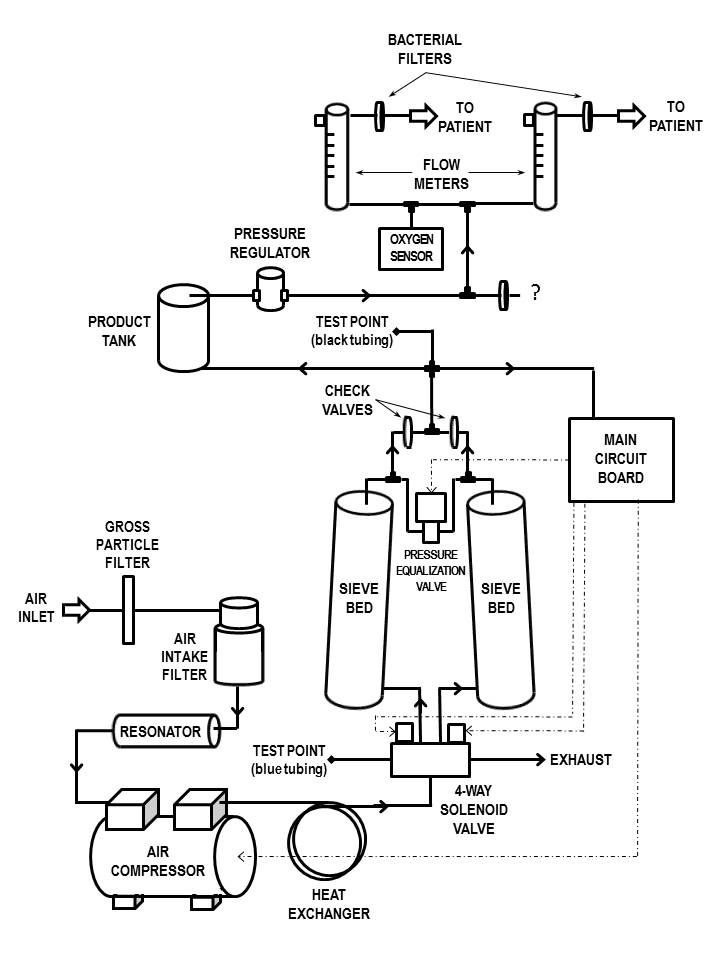
(Pneumatic Diagram of the AirSep Oxygen Concentrator. Email cjo4@rice.edu with comments)